 Fraunhofer UMSICHT Institute Branch Sulzbach-Rosenberg
Project eleMeMe: Latent heat storage for thermal management of a methanol fuel cell

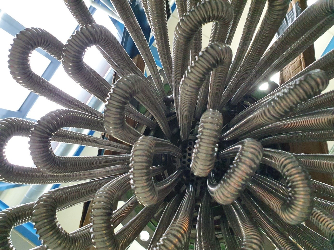

In the joint project eleMeMe (Decentralized decoupling of power generation and energy supply by coupling onsite electrochemical methanol production and methanol fuel cells), Fraunhofer UMSICHT and Fraunhofer IGB jointly developed a latent heat storage system that served as the central element for the thermal management of a high-temperature methanol fuel cell (HT-MFC).
Task: Methanol fuel cell + latent heat storage
eleMeMe pursued the goal of chemically storing surplus renewable electricity and making it usable again at a later time: CO₂ is converted into methanol using electrical energy; this methanol acts as an energy store and is converted back into electricity in a methanol fuel cell when needed. The CO₂ released in the process is captured in a storage liquid so that it is available again as a feedstock – thus closing the carbon cycle. Within this overall system, Fraunhofer UMSICHT and Fraunhofer IGB developed two sub-aspects: the methanol synthesis and the latent heat storage for the efficient use of the fuel cell's waste heat.
Task of the latent heat storage
A methanol fuel cell must first be preheated back to operating temperature after a period of standstill before it can start safely. Usually, a burner or an electric heater performs this task. In eleMeMe, a latent heat storage unit was to take over this task instead: during fuel cell operation, the storage unit absorbs the waste heat; after a standstill period, it releases this heat in a targeted manner to make the fuel cell ready to start again within a short time. This allows the efficiency of the overall system to be increased through intelligent thermal management.
The thermal balance of the system resulted in a required preheating power of around 1.05 kW in order to bring the fuel cell from ambient temperature to the start-capable temperature of at least 403 K (approx. 130 °C) within one hour. Thermal oil was chosen as the heat transfer fluid, as it offers significantly better heat transfer properties than air. The heat is stored at a temperature level of around 438 K – the temperature level at which the fuel cell is cooled at the same time.
Material selection: HDPE as phase change material
For the required phase change in the range of 393 to 413 K (approx. 120–140 °C), several materials were researched and evaluated, including POLYWAX 2000 and 3000, Licocene PE 4201 P, Linklon HF 700 and sebacic acid.
High-density polyethylene (HDPE) was chosen: it offers a suitable melting temperature and melting enthalpy, is readily available and cost-effective due to large-scale industrial production, its properties can be adjusted by means of additives, it is recyclable and remains stable even in the molten state. Disadvantages are its low thermal conductivity and a comparatively large change in volume during the phase change.
The measurement-based characterization yielded a melting temperature of 402.65 K (approx. 129.5 °C), a melting enthalpy of 207.4 kJ/kg and a crystallization enthalpy of 198.9 kJ/kg. Over 100 cycles on a laboratory scale, only minor deviations in these characteristic values were observed – HDPE thus meets cycle class E of RAL-GZ 896 and is considered cycle-stable within this framework. HDPE therefore belongs to the material class of organic polymers – one of several PCM groups that Fraunhofer UMSICHT has investigated in the medium temperature range alongside sugar alcohols, salt hydrates, paraffins and polyethylene glycols.
Storage concept and design
The storage unit was designed as a tube bundle heat exchanger: the PCM is located in the vessel, while the heat transfer fluid flows through corrugated stainless steel hoses arranged axisymmetrically in two registers, each around 20 metres long. Initially, around 36 kg of HDPE were used, corresponding to a theoretical storage capacity of 2 kWh; later, the mass was increased to 42 kg in order to achieve a higher discharge temperature.
A special feature of the flow arrangement: during charging, the hot fluid flows through the storage unit from the inside outwards, while during discharging the direction is reversed. As a result, the PCM solidifies at the outer edge first and acts like an additional insulating layer that protects the still-liquid inner core from heat losses – a self-insulating effect that was confirmed by flow simulations (CFD). At the same time, the simulations showed that at certain flow velocities turbulence can form in the bulges of the corrugated tubes, impeding heat transfer; the tube geometry was therefore changed from narrowly corrugated to widely corrugated tubes.
For the investigations, a mobile test rig with extensive measurement instrumentation (temperature, pressure and volumetric flow rate upstream and downstream of the storage unit as well as at the fuel cell connections) was set up, enabling a complete energy and mass balance. Bypasses allowed the storage unit and a process thermostat – used as a substitute for the fuel cell during basic characterization – to be flexibly connected and disconnected.
Test results: preheating and charging of the fuel cell
In a systematic parameter variation (storage temperature, volumetric flow rate of the heat transfer fluid, cooling capacity), it was shown that a lower volumetric flow rate and a lower cooling capacity extend the period during which the storage unit delivers temperatures above 373 K – in a reference test, this level was maintained for more than 1.3 hours. Across all parameter variations, a usable energy amount of around 2.5 kWh was consistently available in the actual phase change range – an indication of reliable storage behaviour independent of the operating parameters.
During the targeted preheating of the fuel cell, it reached its highest temperature after only around 32 minutes at a storage starting temperature of 433 K; at a lower starting temperature of 413 K, temperatures above 395 K were nevertheless reached within 30 minutes. In all variants investigated, it was possible to preheat the fuel cell to over 403 K in less than one hour.
In an overall test, the complete cycle was run through: first, the storage unit preheated the fuel cell and discharged in the process; the fuel cell then started up and transitioned into operation. After adjusting the heat removal and the volumetric flow rate, it was possible to recharge the storage unit during ongoing fuel cell operation at a rate of around 3 K per hour using the fuel cell's waste heat. This demonstrated the fundamental functionality of the coupled system consisting of storage unit and fuel cell.
Cycle stability in storage operation
After 37 charging and discharging cycles in the pilot-scale storage unit, no corrosion was observed on the shell material; on the PCM itself, only minor, superficial brownish discolourations occurred, which is an indication of surface oxidation processes. A comparison of the charging energy absorbed between cycle 4 and cycle 37 revealed a loss of 7.3 percent; a supplementary DSC analysis of material samples from the storage unit confirmed a decrease in the melting enthalpy from 209.3 to 196.6 J/g, i.e. around 6.1 percent.
Conclusion
The tests show that a latent heat storage unit using HDPE can provide the power and temperature required for preheating a high-temperature methanol fuel cell within a short time and can at the same time be recharged by the fuel cell's waste heat. The basic principle of an integrated thermal management system as a replacement for a burner or an additional electric heater was thus successfully demonstrated.